|
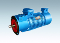
YZRE and YZE series electromagnetic braking motors are composed of YZR and YZE series motors plus direct current electromagnetic brake, which are in compliance with the mechanical industrial codes JB/T7077 and JB/T7563.this series of motors are featured with high overload capability and mechanical strength, compact structure, controllable torque, easy to control, use and maintenance. These motors are suitable for the following work conditions: short time or intermittent running; frequent starting, braking, sometimes have overload lifting and metallurgy equipment translation and driving and braking on hoisting mechanism. Disk type brake is set in the motor, so that the motors have good braking effect.
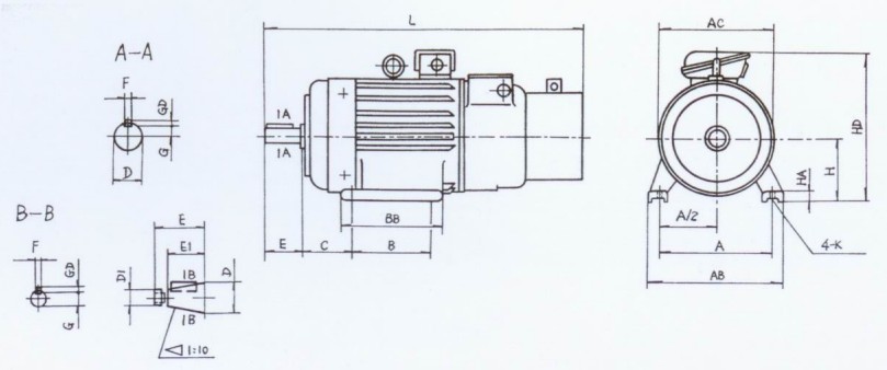
1.IM1001、IM1003 Horizontal installation, Frame with foot end shield without flange motor YZRE112~250
mm
|
Frame
|
Mounting Dimension & Tolerance
|
Overall Dimension
|
|
H
|
A
|
A/2
|
B
|
Difference of B on two sides
|
C
|
Difference of C on two sides
|
K
|
Dia. Of screw
|
D
|
D1
|
E
|
E1
|
Key
|
key way
|
AC
|
AB
|
HD
|
BB
|
L
|
HA
|
|
Dimension
|
Tolerance
|
Dimension
|
Tolerance
|
Dimension
|
Tolerance
|
Dimension
|
Tolerance
|
Dimension
|
Tolerance
|
Dimension
|
Tolerance
|
Dimension |
Tolerance
|
Dimension
|
Tolerance
|
F(h9)
|
GD
|
F(h9)
|
G
|
|
Dimension
|
Tolerance
|
Dimension
|
Tolerance
|
Dimension
|
Tolerance
|
尺寸
|
Tolerance
|
|
112M
|
112
|
0
-0.5
|
190
|
±0.70
|
95
|
±0.50
|
140
|
±0.70
|
0.70
|
70
|
±2
|
0.30
|
12
|
+0.43
0
|
M10
|
32
|
+0.018
+0.002
|
–
|
80
|
±0.37
|
﹣
|
10
|
0
-0.036
|
8
|
0
-0.09
|
10
|
0
-0.036
|
27
|
0
-0.2
|
245
|
250
|
335
|
235
|
700
|
18
|
|
132M
|
132
|
216
|
108
|
178
|
89
|
38
|
33
|
285
|
275
|
365
|
260
|
755
|
20
|
|
160M
|
160
|
254
|
±1.05
|
127
|
±0.75
|
210
|
±1.05
|
1.05
|
108
|
±3
|
0.45
|
15
|
M12
|
48
|
110
|
±0.43
|
14
|
0
-0.043
|
9
|
14
|
0
-0.043
|
42.5
|
325
|
320
|
425
|
290
|
892
|
25
|
|
160L
|
254
|
335
|
934
|
|
180L
|
180
|
279
|
139.5
|
279
|
121
|
55
|
-
|
M36×3
|
82
|
19.9
|
360
|
360
|
465
|
380
|
1026
|
|
200L
|
200
|
318
|
159
|
305
|
133
|
19
|
+0.52
0
|
M16
|
60
|
M42×3
|
140
|
±0.50
|
105
|
16
|
10
|
16
|
21.4
|
405
|
405
|
510
|
400
|
1145
|
28
|
|
225M
|
225
|
356
|
178
|
311
|
149
|
65
|
23.9
|
430
|
455
|
545
|
410
|
1350
|
|
250M
|
250
|
406
|
±1.40
|
203
|
±1.0
|
349
|
±1.40
|
1.40
|
168
|
±4
|
0.60
|
24
|
M20
|
70
|
M48×3
|
18
|
11
|
0
-0.011
|
18
|
25.4
|
480
|
515
|
605
|
510
|
1500
|
30
|
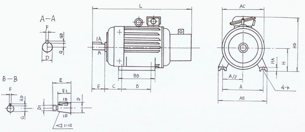
2.IM1001、IM1003Horizontal installation, Frame with foot end shield without flange motor YZE112~250
mm
|
Frame
|
Mounting Dimension & Tolerance
|
Overall Dimension
|
|
H
|
A
|
A/2
|
B
|
Difference of B on two sides
|
C
|
Difference of C on two sides
|
K
|
Dia. Of screw
|
D
|
D1
|
E
|
E1
|
Key
|
key way
|
AC
|
AB
|
HD
|
BB
|
L
|
HA
|
|
Dimension
|
Tolerance
|
Dimension
|
Tolerance
|
Dimension
|
Tolerance
|
Dimension
|
Tolerance
|
Dimension
|
Tolerance
|
Dimension
|
Tolerance
|
Dimension |
Tolerance
|
Dimension
|
Tolerance
|
F(h9)
|
GD
|
F(h9)
|
G
|
|
Dimension
|
Tolerance
|
Dimension
|
Tolerance
|
Dimension
|
Tolerance
|
尺寸
|
Tolerance
|
|
112M
|
112
|
0
-0.5
|
190
|
±0.70
|
95
|
±0.50
|
140
|
±0.70
|
0.70
|
70
|
±2
|
0.30
|
12
|
+0.43
0
|
M10
|
32
|
+0.018
+0.002
|
–
|
80
|
±0.37
|
﹣
|
10
|
0
-0.036
|
8
|
0
-0.09
|
10
|
0
-0.036
|
27
|
0
-0.2
|
245
|
250
|
335
|
235
|
550
|
18
|
|
132M
|
132
|
216
|
108
|
178
|
89
|
38
|
33
|
285
|
275
|
365
|
260
|
625
|
20
|
|
160M
|
160
|
254
|
±1.05
|
127
|
±0.75
|
210
|
±1.05
|
1.05
|
108
|
±3
|
0.45
|
15
|
M12
|
48
|
110
|
±0.43
|
14
|
0
-0.043
|
9
|
14
|
0
-0.043
|
42.5
|
325
|
320
|
425
|
290
|
762
|
25
|
|
160L
|
254
|
335
|
805
|
|
180L
|
180
|
279
|
139.5
|
279
|
121
|
55
|
-
|
M36×3
|
82
|
19.9
|
360
|
360
|
465
|
380
|
862
|
|
200L
|
200
|
318
|
159
|
305
|
133
|
19
|
+0.52
0
|
M16
|
60
|
M42×3
|
140
|
±0.50
|
105
|
16
|
10
|
16
|
21.4
|
405
|
405
|
510
|
400
|
980
|
28
|
|
225M
|
225
|
356
|
178
|
311
|
149
|
65
|
23.9
|
430
|
455
|
545
|
410
|
1170
|
|
250M
|
250
|
406
|
±1.40
|
203
|
±1.0
|
349
|
±1.40
|
1.40
|
168
|
±4
|
0.60
|
24
|
M20
|
70
|
M48×3
|
18
|
11
|
0
-0.011
|
18
|
25.4
|
480
|
515
|
605
|
510
|
1260
|
30
|
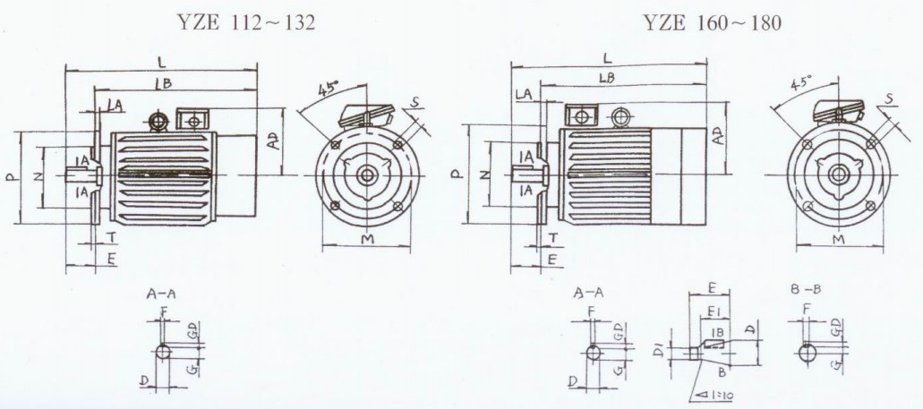
3.IM3001 & IM3003 motor horizontally installer,without footing under base frame and end cover with flange YZRE112~180
mm
|
Base frame numbe
|
Installation dimension and tolerance
|
Outline dimension
|
|
|
M
|
N
|
P
|
T
|
S
|
Bolt
|
D
|
D1
|
E
|
E1
|
Key
|
Keyway
|
L
|
LB
|
AD
|
LA
|
|
F(h9)
|
GD
|
F(N9)
|
G
|
|
Basic dimension
|
Limit deviation
|
Basic dimension
|
Limit deviation
|
Diameter
|
Quantity
|
Basic dimension
|
Limit deviation
|
Basic dimension
|
Limit deviation
|
Basic dimension
|
Limit deviation
|
Basic dimension
|
Limit deviation
|
Basic dimension
|
Limit deviation
|
Basic dimension
|
Limit deviation
|
|
112M
|
FF215
|
215
|
180
|
+0.014
-0.011
|
250
|
4
|
15
|
+0.43
0
|
M12
|
4
|
32
|
+0.018
+0.002
|
-
|
80
|
±0.37
|
-
|
10
|
0
-0.036
|
8
|
0
-0.09
|
10
|
0
-0.036
|
27
|
0
-0.2
|
600
|
610
|
220
|
14
|
|
132M
|
FF265
|
265
|
230
|
+0.016
-0.013
|
300
|
38
|
33
|
750
|
670
|
230
|
|
160M
|
FF300
|
300
|
250
|
350
|
5
|
19
|
+0.52
0
|
M16
|
48
|
110
|
±0.43
|
14
|
0
-0.043
|
9
|
14
|
0
-0.043
|
42.5
|
930
|
820
|
260
|
18
|
|
160L
|
980
|
870
|
|
180L
|
55
|
-
|
M36×3
|
82
|
19.9
|
1050
|
940
|
280
|
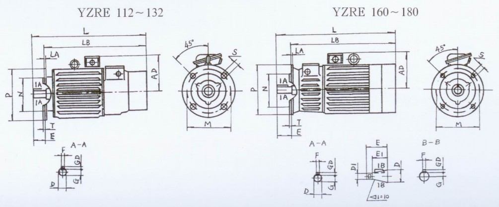
4.IM3001及IM3003 motor horizontally installer,without footing under base frame and end cover with flange YZE112~180
mm
|
Base frame numbe
|
Installation dimension and tolerance
|
Outline dimension
|
|
|
M
|
N
|
P
|
T
|
S
|
Bolt
|
D
|
D1
|
E
|
E1
|
Key
|
Keyway
|
L
|
LB
|
AD
|
LA
|
|
F(h9)
|
GD
|
F(N9)
|
G
|
|
Basic dimension
|
Limit deviation
|
Basic dimension
|
Limit deviation
|
Diameter
|
Quantity
|
Basic dimension
|
Limit deviation
|
Basic dimension
|
Limit deviation
|
Basic dimension
|
Limit deviation
|
Basic dimension
|
Limit deviation
|
Basic dimension
|
Limit deviation
|
Basic dimension
|
Limit deviation
|
|
112M
|
FF215
|
215
|
180
|
+0.014
-0.011
|
250
|
4
|
15
|
+0.43
0
|
M12
|
4
|
32
|
+0.018
+0.002
|
-
|
80
|
±0.37
|
-
|
10
|
0
-0.036
|
8
|
0
-0.09
|
10
|
0
-0.036
|
27
|
0
-0.2
|
565 |
485 |
220 |
14
|
|
132M
|
FF265
|
265
|
230
|
+0.016
-0.013
|
300
|
38
|
33
|
645 |
565 |
230 |
|
160M
|
FF300
|
300
|
250
|
350
|
5
|
19
|
+0.52
0
|
M16
|
48
|
110
|
±0.43
|
14
|
0
-0.043
|
9
|
14
|
0
-0.043
|
42.5
|
870 |
760 |
260 |
18
|
|
160L
|
920 |
810 |
|
180L
|
55
|
-
|
M36×3
|
82
|
19.9
|
1085 |
975 |
280 |
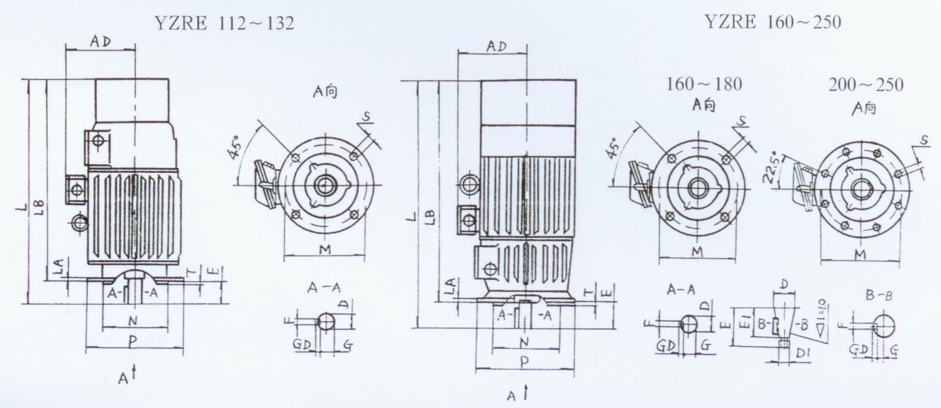
5.IM3011 & IM3013 Install vertical axis toward the docking station without the base, cover flange motor YZRE112~250
mm
|
Base frame numbe
|
Installation dimension and tolerance
|
Outline dimension
|
|
Flang number
|
M
|
N
|
P
|
T
|
S
|
Bolt
|
D
|
D1
|
E
|
E1
|
Key
|
Keyway
|
L
|
LB
|
AD
|
LA
|
|
F(h9)
|
GD
|
F(N9)
|
G
|
|
Basic dimension
|
Limit deviation
|
Basic dimension
|
Limit deviation
|
Diameter
|
Quantity
|
Basic dimension
|
Limit deviation
|
Basic dimension
|
Limit deviation
|
Basic dimension
|
Limit deviation
|
Basic dimension
|
Limit deviation
|
Basic dimension
|
Limit deviation
|
Basic dimension
|
Limit deviation
|
|
112M
|
FF215
|
215
|
180
|
+0.014
-0.011
|
250
|
4
|
15
|
+0.43
0
|
M12
|
4
|
32
|
+0.018
+0.002
|
-
|
80
|
±0.37
|
-
|
10
|
0
-0.036
|
8
|
0
-0.09
|
10
|
0
-0.036
|
27
|
0
-0.2
|
720
|
640
|
220
|
14
|
|
132M
|
FF265
|
265
|
230
|
+0.016
-0.013
|
300
|
38
|
33
|
750
|
670
|
230
|
|
160M
|
FF300
|
300
|
250
|
350
|
5
|
19
|
+0.52
0
|
M16
|
48
|
110
|
±0.43
|
14
|
0
-0.043
|
9
|
14
|
0
-0.043
|
42.5
|
930
|
820
|
260
|
18
|
|
160L
|
980
|
870
|
|
180L
|
55
|
-
|
M36×3
|
82
|
19.9
|
1050
|
940
|
280
|
|
200L
|
FF400
|
400
|
350
|
±0.018
|
450
|
8
|
60
|
M42×3
|
140
|
±0.5
|
105
|
16
|
10
|
16
|
21.4
|
1230
|
1090
|
320
|
20
|
|
225M
|
65
|
23.9
|
1320
|
1180
|
|
250M
|
FF500
|
500
|
450
|
±0.02
|
550
|
70
|
M48×3
|
18
|
11
|
0
-0.11
|
18
|
25.4
|
1550
|
1410
|
355
|
22
|
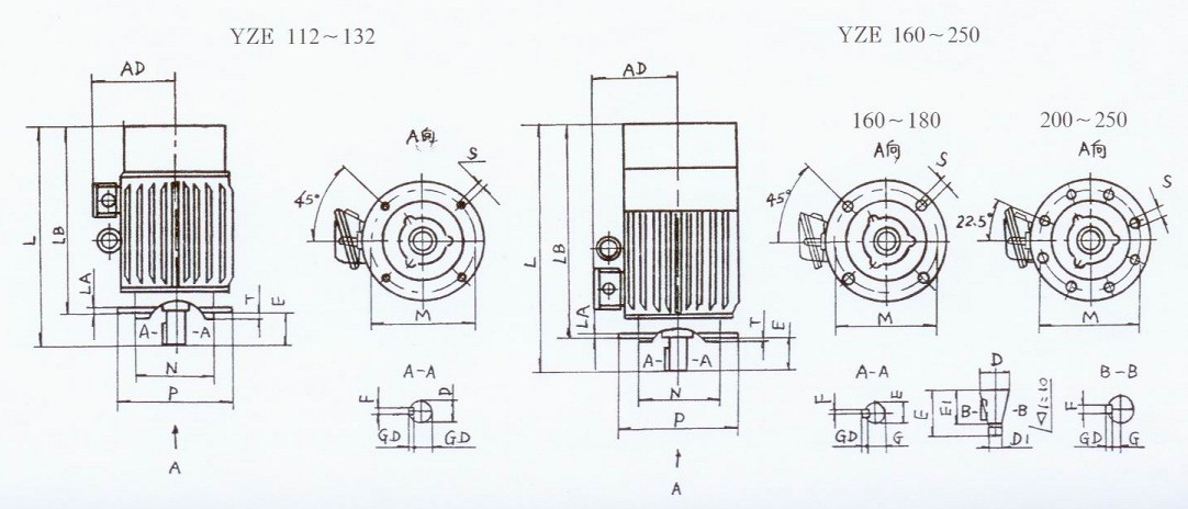
6.IM3011 & IM3013 Vertical installation, the shaft toward the docking station without the dock, cover flange motor YZE112~250
mm
|
Base frame numbe
|
Installation dimension and tolerance
|
Outline dimension
|
|
Flang number
|
M
|
N
|
P
|
T
|
S
|
Bolt
|
D
|
D1
|
E
|
E1
|
Key
|
Keyway
|
L
|
LB
|
AD
|
LA
|
|
F(h9)
|
GD
|
F(N9)
|
G
|
|
Basic dimension
|
Limit deviation
|
Basic dimension
|
Limit deviation
|
Diameter
|
Quantity
|
Basic dimension
|
Limit deviation
|
Basic dimension
|
Limit deviation
|
Basic dimension
|
Limit deviation
|
Basic dimension
|
Limit deviation
|
Basic dimension
|
Limit deviation
|
Basic dimension
|
Limit deviation
|
|
112M
|
FF215
|
215
|
180
|
+0.014
-0.011
|
250
|
4
|
15
|
+0.43
0
|
M12
|
4
|
32
|
+0.018
+0.002
|
-
|
80
|
±0.37
|
-
|
10
|
0
-0.036
|
8
|
0
-0.09
|
10
|
0
-0.036
|
27
|
0
-0.2
|
565 |
485 |
220
|
14
|
|
132M
|
FF265
|
265
|
230
|
+0.016
-0.013
|
300
|
38
|
33
|
645 |
565 |
230
|
|
160M
|
FF300
|
300
|
250
|
350
|
5
|
19
|
+0.52
0
|
M16
|
48
|
110
|
±0.43
|
14
|
0
-0.043
|
9
|
14
|
0
-0.043
|
42.5
|
870 |
760 |
260
|
18
|
|
160L
|
920 |
810 |
|
180L
|
55
|
-
|
M36×3
|
82
|
19.9
|
1085 |
975 |
280
|
|
200L
|
FF400
|
400
|
350
|
±0.018
|
450
|
8
|
60
|
M42×3
|
140
|
±0.5
|
105
|
16
|
10
|
16
|
21.4
|
1170 |
1030 |
320
|
20
|
|
225M
|
65
|
23.9
|
1320 |
1180 |
|
250M
|
FF500
|
500
|
450
|
±0.02
|
550
|
70
|
M48×3
|
18
|
11
|
0
-0.11
|
18
|
25.4
|
1360 |
1220 |
355
|
22
|
|
