 |
|
mm
|
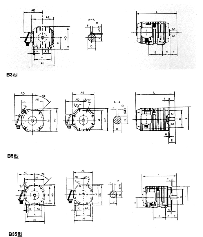
| B3 type (Foot-Mounted,without Flange)Motor |
|
Frame
|
No. of poles
|
Mounting Dimension
|
Overall Dimension
|
|
A
|
A2
|
B
|
C
|
D
|
E
|
F
|
G
|
H
|
K
|
AB
|
AE
|
AD
|
HD
|
L
|
|
YG112L
|
4.6.8.10.12
|
190
|
95
|
159
|
70
|
32
|
80
|
10
|
27
|
112
|
12
|
235
|
240
|
205
|
240
|
445
|
|
YG132M
|
6.8.10.12.16
|
216
|
108
|
178
|
89
|
38
|
33
|
132
|
265
|
265
|
220
|
265
|
495
|
|
YG160S
|
6.8.10.12.16
|
254
|
127
|
108
|
48
|
110
|
14
|
42.5
|
160
|
15
|
315
|
315
|
250
|
320
|
570
|
|
YG160L
|
6.8.10.12.16
|
254
|
690
|
|
YG180L
|
8.10.12.16.20
|
279
|
139.5
|
279
|
121
|
55
|
16
|
49
|
180
|
360
|
360
|
295
|
365
|
730
|
|
YG200L
|
10.12.16.20
|
318
|
159
|
305
|
133
|
65
|
140
|
18
|
58
|
200
|
19
|
415
|
415
|
320
|
415
|
780
|
|
YG225M
|
10.12.16.20
|
356
|
178
|
311
|
149
|
75
|
20
|
67.5
|
225
|
470
|
470
|
335
|
465
|
835
|
|
| Note:1.GE=D-G,GE Tolerance is( |
+0.20 |
) |
| 0 |
mm
|
|
B5 type (Flange -Mounted,without Foot)Motor
|
|
Frame
|
No. of poles
|
Mounting Dimension
|
Overall Dimension
|
|
D
|
E
|
F
|
G
|
M
|
N
|
P
|
R
|
S
|
T
|
flange hole counting
|
AE
|
AD
|
HD
|
L
|
|
YG112L
|
4.6.8.10.12
|
32
|
80
|
10
|
27
|
215
|
180
|
250
|
0
|
15
|
4.0
|
4
|
240
|
205
|
240
|
445
|
|
YG132M
|
6.8.10.12.16
|
38
|
33
|
265
|
230
|
300
|
265
|
220
|
285
|
495
|
|
YG160S
|
6.8.10.12.16
|
48
|
110
|
14
|
42.5
|
300
|
250
|
350
|
19
|
5.0
|
315
|
250
|
335
|
570
|
|
YG160L
|
6.8.10.12.16
|
690
|
|
YG180L
|
8.10.12.16.20
|
55
|
16
|
49
|
360
|
295
|
355
|
730
|
|
YG200L
|
10.12.16.20
|
65
|
140
|
18
|
58
|
400
|
350
|
450
|
8
|
415
|
320
|
450
|
780
|
|
YG225M
|
10.12.16.20
|
75
|
20
|
67.5
|
470
|
335
|
465
|
835
|
|
| |
| Note:1.GE=D-G,GE Tolerance is ( |
+0.20 |
) |
| 0 |
2.P dimension is max。
3.R is distance from flange mating face to shoulder of main shaft. |
|
B35 type (Foot-Mounted or Flange-Mounted)Motor
mm
|
|
Frame
|
No. of poles
|
Mounting Dimension
|
Overall Dimension
|
|
A
|
A/2
|
B
|
C
|
D
|
E
|
F
|
G
|
H
|
K
|
M
|
N
|
P
|
R
|
S
|
T
|
flange hole counting
|
AB
|
AE
|
AD
|
HD
|
L
|
|
YG112L
|
4.6.8.10.12
|
190
|
95
|
159
|
70
|
32
|
80
|
10
|
27
|
112
|
12
|
215
|
180
|
250
|
0
|
15
|
4.0
|
4
|
235
|
240
|
205
|
240
|
445
|
|
YG132M
|
6.8.10.12.16
|
216
|
108
|
178
|
89
|
38
|
33
|
132
|
265
|
230
|
300
|
265
|
265
|
220
|
290
|
495
|
|
YG160S
|
6.8.10.12.16
|
254
|
127
|
108
|
48
|
110
|
14
|
42.5
|
160
|
15
|
300
|
250
|
350
|
19
|
5.0
|
315
|
315
|
250
|
345
|
570
|
|
YG160L
|
6.8.10.12.16
|
254
|
48
|
690
|
|
YG180L
|
8.10.12.16.20
|
279
|
139.5
|
279
|
121
|
55
|
16
|
49
|
180
|
360
|
360
|
295
|
365
|
730
|
|
YG200L
|
10.12.16.20
|
318
|
159
|
305
|
133
|
65
|
140
|
18
|
58
|
200
|
19
|
400
|
350
|
450
|
8
|
415
|
415
|
320
|
430
|
780
|
|
YG225M
|
10.12.16.20
|
356
|
178
|
311
|
149
|
75
|
20
|
67.5
|
225
|
470
|
470
|
335
|
465
|
835
|
|
| |
| Note:1.GE=D-G,GE Tolerance is( |
+0.20 |
) |
| 0 |
|
2.P dimension is max.
3.R is distance from flange mating face to shoulder of main shaft. |
| |
